CHINESE
 ENGLISH


What Is The Polarity Of LED Lights?
Polarity is the direction of current flow within an LED light or any electrical device. It is indicated by positive (anode) and negative (cathode) terminals. You need to maintain consistency in polarity while connecting LED lights to the power source. A wrong polarity will hinder the current flow, and lights will not glow.
Want to know more about the polarity of LED lights? Read this article, and you will always go right with LED light installation. I’ve mentioned some effective methods of detecting the polarity of LEDs. So, why wait any more? Get into the discussion,
What Do You Mean By The Polarity Of LED Lights?
The current flow within an LED light or diode has a definite direction, indicated by its polarity. Like any other electrical component, an LED light has a positive (+) and negative (-) end. The positive end is called the anode, and the negative end is called the cathode. Electricity flows from the anode towards the cathode, essential for the LED emitting light. This directionality is known as the polarity of an LED light.
You can consider polarity as the two poles of an LED light, where one pole is positive (anode) and the other is negative (cathode). You must maintain this polarity while installing the light to ensure the light glows.
You need to connect the positive end of the LED light (the anode) to the positive end of the driver or power source and the negative end of the light (the cathode) to the negative end of the source. If the polarity is not maintained, the light will not glow.
How Does the Polarity Of LED Light Work?
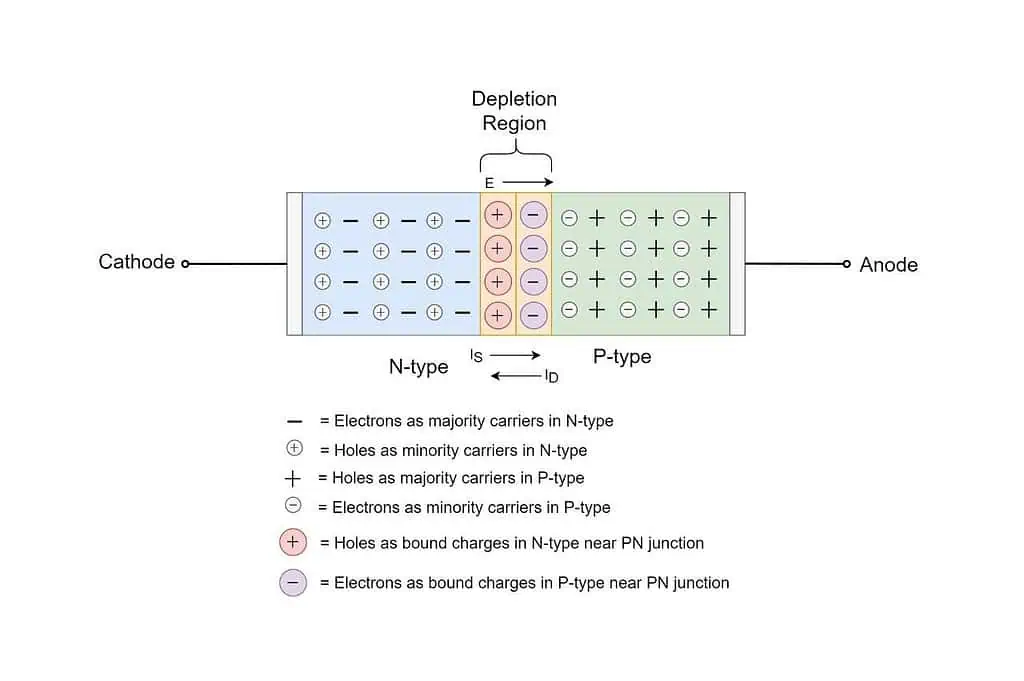
LED lights are made of semiconductors through which the current flows. However, the mechanism of the current flow of the semiconductor is different from that of regular wire. In a semiconductor, a P-N junction is created by doping impurities. These impurities are classified into two variants- p-type material and n-type material.
The materials used as impurities to create an abundance of holes (positive charge carriers) in the semiconductor are known as p-type materials. On the other hand, n-type material refers to materials that provide an excess of electrons (negative charge carriers). The spot where these p-type and n-type materials meet is called the P-N junction. It ensures the electricity flows in one way, blocking the reverse direction.
Each LED has two ends: the anode (positive) and the cathode (negative), corresponding to the p and n regions. Once you connect the anode to the positive terminal and the cathode to the negative terminal of the power source, the current starts to flow. As the current passes, the electrons from the n-type material move towards the p-type material. Similarly, the holes from the p-type material move towards the n-type material. The electrons combine with the holes as they move across the P-N junction. This recombination releases energy through photons, which we see as light.
NB: Electrons flow in the opposite direction of the current flow.
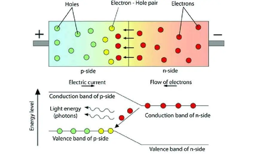
However, the light’s color depends on the LED’s semiconductor. They have conduction and valence bands on both the p and n sides. The difference between these bands is called band gaps. When electrons fall from the conduction band to the valence band during the recombination process, energy is released as light.
This emitted light energy is equal to the band gap of the semiconductor. The band gap varies for different semiconductors. That is why different semiconductors are used in LEDs to bring different light colors. For example, Gallium Phosphide (GaP) produces red, yellow, or green light, while Gallium Nitride (GaN) is used for blue and white LEDs.
Is Polarity Important For LEDs?
Maintaining polarity is essential for LEDs. A reverse polarity will ruin the circuit, and your LED lights will not glow. LED stands for Light Emitting Diodes. Like all other diodes, LED allows electricity to flow only in one direction. This is only possible when you set the light to follow the correct polarity.
To illuminate the LEDs, you must join the light’s positive end to the power source’s positive end. Similarly, the negative end of the light should be connected to the negative end of the power source. This will ensure current flows in the desired direction, enabling electrons to recombine and emit light.
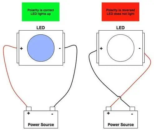
If the polarity is not maintained, if you connect positive to negative or vice versa, the LED will block the current. The P-N junction will have a prevalent current flow, and the lights will not glow. Though the LEDs are not damaged due to reverse polarity, this will hamper the circuit design. Yet, in some cases, applying reverse voltage beyond the LED’s reverse voltage rating can damage the LED.
How To Detect Polarity of LED Lights?
Some physical features of LED lights will help you detect their polarity. If you can’t find out, there are other ways too; let’s discuss them all:
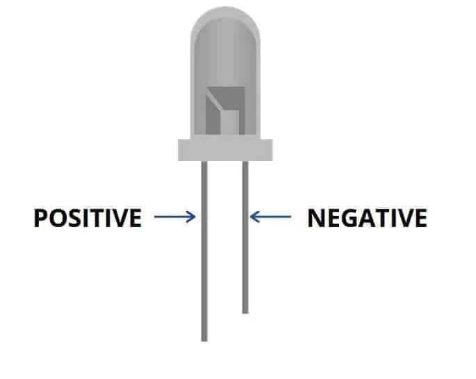
Method 1: Check Leads’ Length
If you look at the diode, two legs or leads are visible. You can distinguish the leg lengths easily. The longer lead is the anode (positive terminal), and the shorter is the cathode (negative terminal). However, this is not a foolproof way of detecting polarity. The legs might have been cut or soldered to fit the installation without a brand-new LED. In this case, how will you identify the polarity of the LED? Follow the next method for this.
Method 2: Look For Flat Edge & Round Side
Keep your eye on the transparent plastic casing to find a flat or round edge. LEDs have flat edges near the negative leg and round edges on the positive side. This is a helpful clue for detecting polarity.

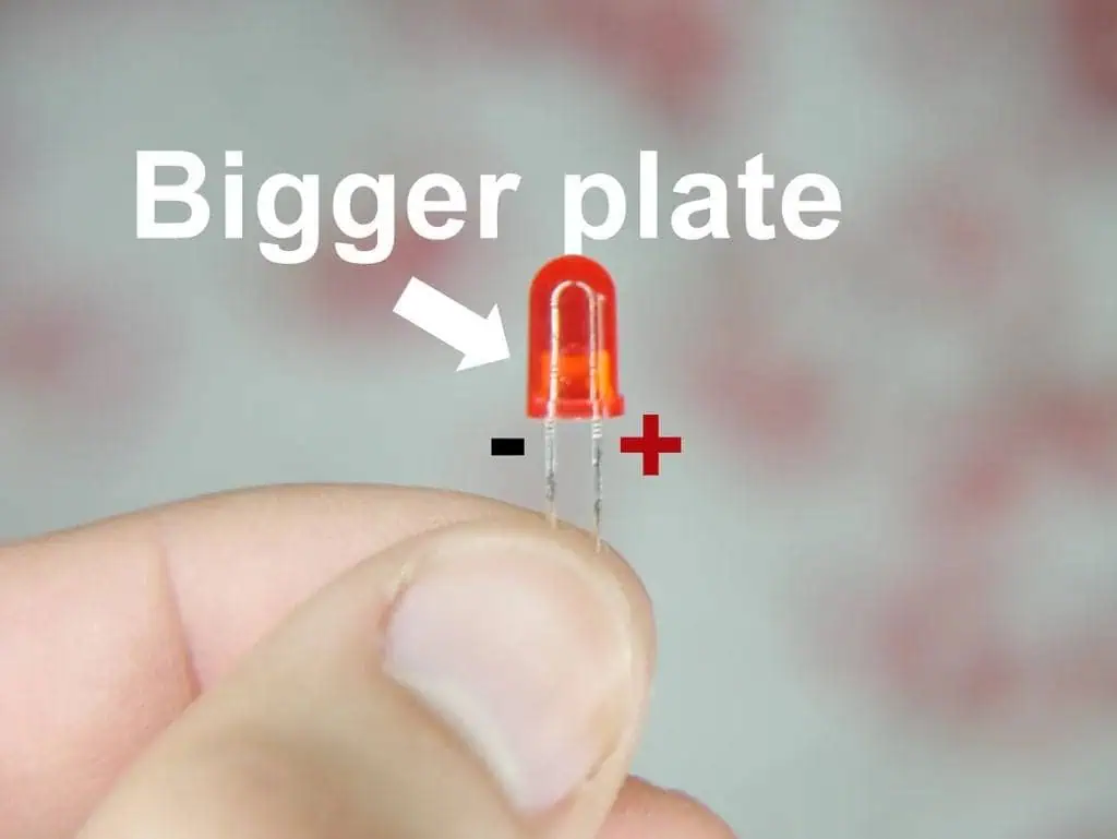
Method 3: Detect The Difference in Plate
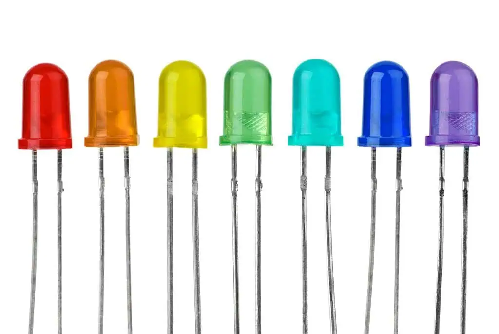
Give a closer look inside the LED casing; they can be clear, red, green, yellow, blue, etc. But these are mostly transparent, so you can easily see inside. You will find two metal plates of different sizes. The bigger plate is connected to the LED’s negative lead, the cathode. The smaller plate is connected to the positive lead, an LED anode. Thus, if you can’t distinguish them by observing the leads/legs, use this technique.
Method 4: Use Multimeter
A multimeter is an electrical device used for diode tests, voltage, current, resistance measurement, etc. It has two probes (red for positive and black for negative) and a digital display. To detect the polarity, you must set the multimeter in the diode test mode, usually symbolized as (▶|–).
NB: If your multimeter does not have a diode mode, you can use the resistance mode (Ω).
Once the mode is set, connect the red probe to the positive input terminal of the multimeter (often labeled VΩmA or similar). Similarly, insert the black probe into the negative or common terminal of the multimeter (labeled COM).
Test the LED by touching the red probe to one LED lead and the black probe to the other. The light will glow up dimly if the red probe is connected to the anode (positive terminal) and the black probe is connected to the cathode (negative terminal).
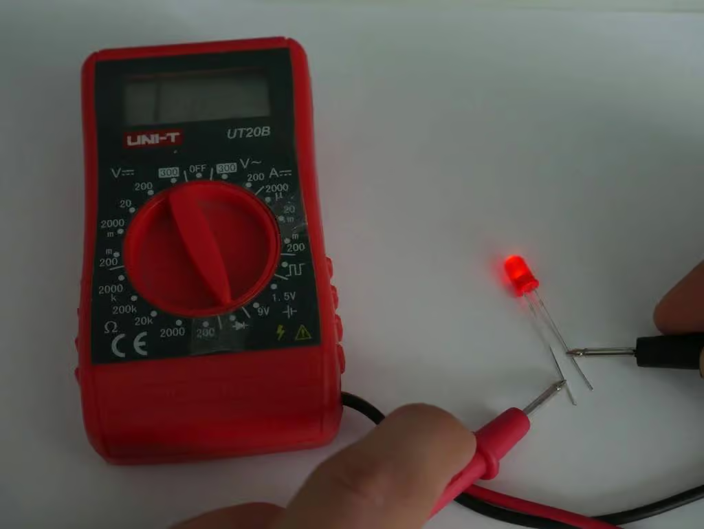
However, if the light is not illuminating, the probes don’t match the correct polarity. Reverse the probes by touching red to the other lead and black to the remaining one; you will find the light glowing. This way, you can detect the positive and negative end of the LED.
Method 5: Use A Coin Cell Battery
Using a coin cell battery like a CR2032, you can quickly determine an LED’s positive and negative legs. For this, you need to place the legs of the LED on the terminals of the coin cell battery, as shown in the figure below. If the light dimly glows, it means the leg touching the battery’s positive side is the anode (positive) of the LED. And the leg touching the battery’s negative terminal is the cathode (negative) of the LED. If it doesn’t light up, flip the LED and try again.
What Happens If You Wire LED Lights Backwards?
If you wire LED lights backward, the light will not glow up. However, it will not cause any harm to the LED. If you attempt a wrong connection by mistake, nothing will panic when the voltage is low to medium. But if your LEDs are connected to a high-voltage circuit, a wrong connection can damage the LED. So, if you accidentally connect the LED lights in reverse or backward, correct them ASAP.
However, sometimes reverse diodes are included in the circuit as a protection measure. The forward voltage drop across the reverse diode is typically very low (around 0.7V for a standard silicon diode). This voltage is too weak to damage the diode. It effectively protects the LED from the high reverse voltage that could exceed its reverse breakdown voltage.
How To Identify The Polarity Of LED Strip Light?
Observing the PCB’s marking lets you visually detect the LED strip’s polarity. LED strips have copper pads. On each copper pad, symbols indicate polarity; you will find ‘+’ and ‘-‘ markings. For instance, a white or single-color LED strip has positive and negative markings; you can connect the driver or power source following this polarity order.
Besides this, it will also guide you in maintaining polarity while connecting multiple LED strips together.

However, all variants of LED strips don’t have the same polarity indication. For instance, tunable white strips might have markings like ‘C+’ and ‘W+’ instead of ‘+’ and ‘-.’ Again, an RGB LED strip with a common anode has a single positive terminal (anode) shared by all three colors (Red, Green, Blue). You need to connect the positive terminal (+) to the positive side of the power supply. The individual color channels (R, G, B) are connected to the ground (negative) through a controller or directly. The chart below will help you to clear the concept:
|
LED Strop Polarity Chart |
||||
|
LED Strip Type |
Positive (+) |
Negative (-) |
Additional Channels |
Wire Color (Typical) |
|
+ or V+ |
– or GND |
None |
Red (Power), Black (Ground) |
|
|
C+ (Cool White), W+ (Warm White) |
Shared Ground |
None |
Varies (Cool White, Warm White) |
|
|
RGB LED Strip (Common Anode) |
+ (Common Anode) |
R- (Red), G- (Green), B- (Blue) |
Individual channels connect to the ground |
Red (Power), Green (Ground for G), Blue (Ground for B), Varies (Ground for R) |
|
RGB LED Strip (Common Cathode) |
– (Common Cathode) |
R+ (Red), G+ (Green), B+ (Blue) |
Individual channels connect to positive |
Black (Ground), Red (Power for R), Green (Power for G), Blue (Power for B) |
|
+ (Power) |
– (Ground) |
DI (Data In), CI (Clock In) (if applicable) |
Red (Power), Black (Ground), Varies (Data, Clock) |
|
NB: The wire color and polarity symbols may vary for different brands or manufacturers.
Apart from visually checking the direction, you can use a multimeter to detect the polarity of LED strips. Set the multimeter to continuity mode. Then, place the multimeter probes on the copper pads of the LED strip. A beep sound from the device indicates current flowing in the forward direction (positive to negative through the LED). This confirms the correct polarity.
Troubleshooting Common LED Strip Polarity Issues
While setting up or wiring LED strip lights, here are the common issues you might face with polarity:
Difficulty In Finding the Polarity Mark
The polarity marks are printed very minutely on the PCB, and some may not have any marking. These markings can be too tiny for narrow strips that you may need help to read. If you can’t find them, use a microscope. If there are no marks at all, use a multimeter. Thai devices will quickly detect the polarity of the LED strip.
Wrong Polarity: Light Not Glowing
If you connect the LED strip light’s negative terminal to the power supply’s negative end or the positive to the positive, the light will not glow. Take off the connections and redo it with the correct polarity.
Loose Connection Causing Flickering
Even if your polarity is correct, the light may show flickering issues. This can be due to several reasons, such as a loose connection being the most common. When the LED strips are connected to the power supply, if the wiring becomes loose, the LED will go through flickering issues. For this, recheck the joints and make sure they are apt for a strong connection.
Wiring Compatibility Issues
LED strip connectors are used when joining one LED strip to the other or simply connecting LED strips to the power source. Every LED strip variant has a specific LED strip connector requirement. For instance, if you use a single-color LED strip, you need a 2-pin LED strip connector. If you use the same connector for the RGB LED strip, the light will not glow even if you maintain polarity. In this case, you need to use 4 PINs LED strip connectors.
Conclusion
Knowing the polarity order is necessary for wiring or connecting any electrical devices, including LED lights. To complete the circuit and ensure the light glows, you need to connect the light’s positive terminal to the positive end and the negative terminal to the power supply’s negative end. If it’s a through-hole LED with two leads and a head cap, the longer leg is positive. You can also detect this by following the flat and sound side or the size of the plate, as I mentioned in the discussion.
However, if you are working with SMD (Surface-Mount Device) LEDs like in LED strips, you can quickly follow the symbols to find the polarity. The SMDs are arranged in a printed circuit board with ‘+’ and ‘-‘ markings indicated.
These marks will guide you in connecting the LED light to the power supply with the correct polarity. In this case, you can go for our LED strip lights. All our fixtures have clear printed polarity markings with the copper pad. Thus, you can easily install the light without any professional help or requirement of a multimeter to detect polarity!
FAQ
Contact Us

Name: HHP LIGHTING
Tel: +86-15889542485
E-mail: info@hhp-lighting.com
Skype: cherrychen.HHP
WeChat: +8615889542485
Whatsapp: +8613923945492
Add: 2F 5Bldg, HuiKe Industrial Park, Shiyan Town, Bao'an District, Shenzhen, China . 518108


 Skype Chat
 WhatsApp
  Mail inquiry